
As explained in this post, it is possible to estimate a value for the earthing resistance of an electrode (or set of electrodes, as is applicable for an overhead line tower) using a simple formula. This method is called the geometric and contact resistance method. In the article below we explain the method using transmission line towers.
What is the geometric and contact resistance method?
The name already explains this consists of two parts: the tower footing resistance consists of the Geometric resistance + Contact resistance.
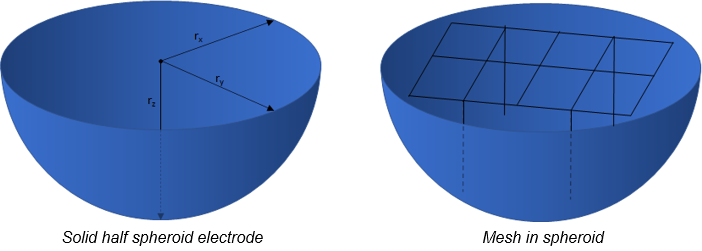
If you assume the electrodes to be a solid (half) spheroid electrode, the geometric resistance can be estimated with a simple formula. An improvement of this estimation is possible by introducing another aspect, to correct for the fact that the ground electrode under review is not solid, but consists of a set of conductors or wire frames. In other words, the earthing structure is limited in terms of contact to its surroundings. This is translated into a contact resistance.
This is graphically presented in the picture below. On the left the solid half spheroid is given, representing the geometric resistance. On the right the meshed earthing structure is shown. This mesh makes less contact to its surrounding soil, and therefore will result in a higher soil resistivity.
The geometric and contact resistance method in formulas
For those who like to calculate this, the formula for the geometric resistance is as follows:

Where,
ρe = the soil resistivity
g = the geometric sum of electrode radii
Q = the shape factor
A= the outer surface area of the equivalent solid electrode
And
The formula for the contact resistance is:

Where,
ρ1 = the upper layer resistivity
L = the total length of the wire
A = the outer surface area of the equivalent solid electrode
Awire = the surface area of the actual electrode (contact to soil)
Example for a transmission tower
You can find an example of the geometric and contact resistance method in the following part. The method is applied to a tower. The figures show how the situation is practically translated.
Geometric resistance
The shape, and therefore the surface of the half spheroid, is determined by the basic foundation geometry, as displayed in the figure below for two different towers

As you may have guessed, based on the graphical representation, the tower on the right will have a lower earthing resistance. This is due to 2 reasons:
1. the contact surface of the half spheroid to the surrounding soil is larger
2. the total length of conductor (mesh) is larger, since the foundation poles are longer.
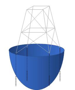
Contact resistance
The geometric resistance determines the main part of the applicable earthing resistance value. As a second step, the contact resistance shall be added to get the requested resistance value. In essence, this contact resistance value is a correction value to take into account that the spheroid is not a solid object, but in fact exists of a wire frame, as shown below.
Example calculation:
- soil resistivity: 200 Ohm.m
- Length of foundation poles: 4m
- Distance between legs: 10m
- Foundation pole radius: 0.2m
Results in a:
- Electrode resistance: 5.5 Ohm
- Contact resistance: 3.3 Ohm
- Total earthing resistance: 8.8 Ohm
Applicability
Checks with commercial software show an accuracy of 3 to 6%, therefore the accuracy is indicated to be +-10%. This method is applicable to uniform soil layers only.
Do you want to become an expert on this topic? We offer two relevant online courses:
- This course on the measurement and determination of geo electric soil characteristics, the calculation of soil potentials and touch voltages
- This course on the measurement and estimation of the earthing resistance of an overhead line tower.
References
[1] researchgate.net – Contact and geometric resistance
[2] ieee.org – PES2015_Update_2010TD0683