Basically, three methods are often used to estimate or calculate the earthing resistance of an earthing system. This can be the foundation of an transmission line tower, the earthing grid of a high voltage substation of other conducting parts in the soil.
The three most common methods are:
- Analytical expressions
- Geometric and contact resistance method
- Numerical methods
Analytical expressions
Analytical expressions are formula’s that are derived to be used for typical shapes of electrodes. Different sources like books, articles and other literature can provide you with these formula’s.
This typically concerns a simple formula that allows you to calculate an earthing resistance value based on a few input parameters. This is widely used for small earthing constructions, such as a single rod, one or more vertical conductors in the soil, etcetera.
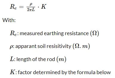
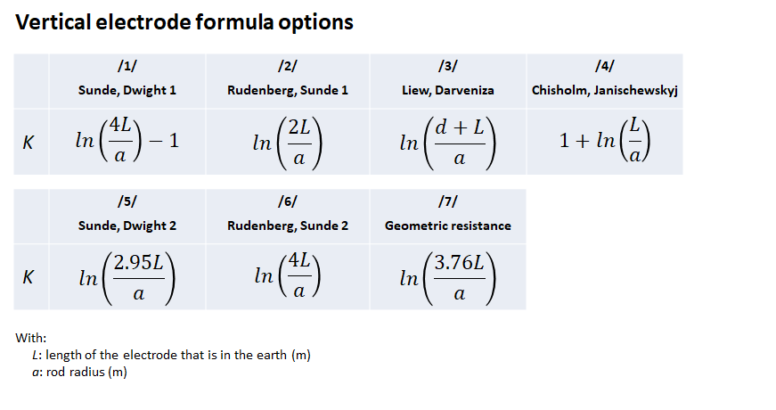
So, which formula is the best? This depends on the use. Formula /1/ seems to be most referenced in literature and standards and is therefore a good option to apply in studies. For example, std.IEEE80 refers to formula /1/ and std.IEEE81 mentions both /1/ and /2/. In addition, formula /1/ gives nearly identical results as formula /6/ and similar results as formula /7/. So, this seems to be a good choice.
On the other hand, a simple comparison with commercial software shows that the outcome with this formula is often overestimated. Formula /3/ however matches best in the comparison, but in its turn has a slight underestimation of the outcome.
Please note that this formula does not allow you to take soil layering into account.
Geometric and contact resistance method
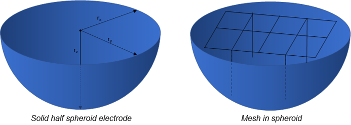
The geometric and contact resistance method can also be used. The name already explains this consists of two parts: the tower footing resistance consists of the Geometric resistance + Contact resistance.
Basically you calculate the earthing resistance of a half spheroid electrode, and then correct for the error that you make by not using a mesh, as shown in the figure below.
This method is estimated to be ±10% accurate compared to commercial software. The application of this method is described in more detail here.
Also this method only takes a uniform soil as a basis. For more complex situations, dedicated software is recommended.
Numerical methods
Numerical methods are often applied in commercial software. For detailed calculations of complex electrode shapes and multi layer soil models we advise you to use a commercial software package. There are several options in the market, all with their own options and features.

We do not advise which software is best. Just make sure that if you are going to perform calculations for large earthing structures, the software is able to take conductor impedance and mutual coupling into account.
Summary
It is possible to make some rough estimations to calculate the earthing resistance of an earthing structure, but also to model it in detail in (commercial) software. There is also an intermediate option, called the geometric and contact resistance method.
Do you want to become an expert on this topic? We offer two relevant online courses:
- This course on the measurement and determination of geo electric soil characteristics, the calculation of soil potentials and touch voltages
- This course on the measurement and estimation of the earthing resistance of an overhead line tower.